
Making a smart doorbell - part one


As regular readers will know, I'm getting more interested in home automation and have had Home Assistant running in the house for a while (it's just been doing very little). Unfortunately, my plan to use a humidity sensor to check for leaks came to nothing[1] but now I've got Home Assistant doing something useful - a smart doorbell. In this case I've retrofitted my existing doorbell (push button which connects an electromagnet to then ring an actual bell) to be controlled via Home Assistant.
This project is based on work by Franck "Frenck" Nijhof with his original blog post here (archived here).
Parts list
- Micro controller: ESP-01S
- Relay module: TeOhk ESP8266
- USB phone charger (5 volts)
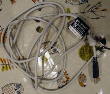
- Long USB cable to deliver power
- Existing doorbell plus its wiring and button
- Dupont wires (wires with an rectangular connector on the end, like you'd connect to a PC motherboard)
- FTDI adapter to flash the firmware
Initial build
I started off with a proof of concept build having ordered the parts I was missing. Fortunately I was able to re-use a salvaged USB cable I'd taken off an old webcam from my "I'll keep that, might need it one day" box - a good feeling.
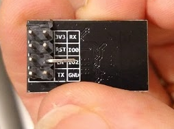
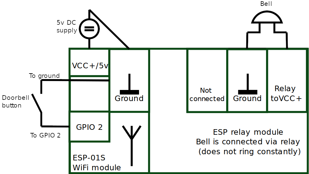
Next it was necessary to bend one of the GPIO pins on the ESP micro controller so we can connect a dupont wire to it. This wire gets connected to the doorbell's button so that when the button is pushed, completing the circuit, the relay is triggered to ring the bell. As the button is now connected to the micro controller we can also set rules so the bell will only ring at certain times. Automations also become possible because Home Assistant is aware of the push button event. Be careful while bending the pin - bending it too much can snap it.
Creating the firmware
Firmware is software that controls a piece of hardware, in this case the micro controller. Our firmware will allow us to have the doorbell join our WiFi network and permit remote control / sending of events to Home Assistant. We make the firmware using the ESP Home add-on for Home Assistant and Frenck explains this process nicely on his site, so I won't repeat it here. Make sure to modify the code to suit your environment - code available on Frenck's GitHub. Once the code is customised and built, download it so we can flash (apply or install) it to the micro controller.
Flashing the ESP with ESPflasher
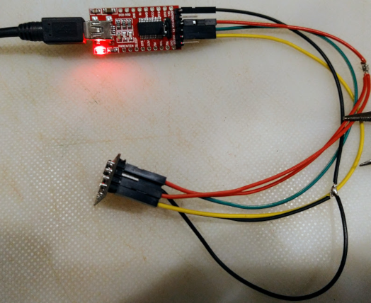
Connect the FTDI flasher to the ESP chip
It's important to note that not all FTDI tools have the headers in the same order, so you'll need to confirm your wiring. Some pins are linked to two others so you'll need to make up some Y cables for this purpose - the photo below shows my not too elegant solution. Make sure your FTDI tool is set to 3.3V and that you've wired it according to the wiring diagram.
FTDI --> ESP pin
-------------------------------
GND  --> GND
      \> GPIO-2
CTS  --> Not connected
VCC  --> CH_PD (Chip Powerdown)
      \> VCC (3.3V)
TX   --> RX
RX   --> TX
DTR  --> Not connected

Note that TX (transmit) connects to RX (receive) and vice versa.Flash the image
First download the ESP flasher tool from https://github.com/esphome/esphome-flasher, making sure to download the version for your operating system. I'm running Linux on all my devices so downloaded an Ubuntu compatible version. Trying to run the program resulted in a "permission denied" error, which is a little cryptic:
# Just trying to run the file will fail:
$ ./ESPHome-Flasher-1.3.0-Ubuntu-x64.exec
bash: ./ESPHome-Flasher-1.3.0-Ubuntu-x64.exec: Permission denied
What we're being told is that the execute permission is missing, although that's not immediately obvious. We apply the execute permission so the tool will run:
# Set the file to be executable:
$ chmod +x ./ESPHome-Flasher-1.3.0-Ubuntu-x64.exec
# Now you can run the file, opening the GUI:
$ ./ESPHome-Flasher-1.3.0-Ubuntu-x64.exec
You might get an error accessing the serial port, in which case you need to sudo (sudo ./ESPHome-Flasher-1.3.0-Ubuntu-x64.exec).
Using '/dev/ttyUSB0' as serial port.
Unexpected error: [Errno 13] could not open port /dev/ttyUSB0: [Errno 13] Permission denied: '/dev/ttyUSB0'
Follow the on-screen instructions, or Frenck's guidance, and you should end up with output similar to the below:
Using '/dev/ttyUSB0' as serial port.
Connecting....
Detecting chip type... ESP8266
Connecting...

Chip Info:
 - Chip Family: ESP8266
 - Chip Model: ESP8266EX
 - Chip ID: 0033AB4C
 - MAC Address: EC:FA:BC:33:AB:4C
Uploading stub...
Running stub...
Stub running...
Changing baud rate to 460800
Changed.
 - Flash Size: 1MB
 - Flash Mode: dout
 - Flash Frequency: 40MHz
Erasing flash (this may take a while)...
Chip erase completed successfully in 3.1s
Compressed 446848 bytes to 305276...
Writing at 0x00048000... (100 %)Wrote 446848 bytes (305276 compressed) at 0x00000000 in 7.1 seconds (effective 502.4 kbit/s)...
Hash of data verified.

Leaving...
Hard Resetting...
Done! Flashing is complete!

Showing logs:
Connecting the ESP to the doorbell
Sadly I didn't take too many pictures of the connection stage, but below is what my proof of concept looked like once assembled. The button wires connect to one of the terminal blocks plus to the red wire that's connected to the bent pin on the underside of the ESP. A second set of terminals connects to the bell itself so when the button is pressed it will ring (even without Home Assistant being configured).
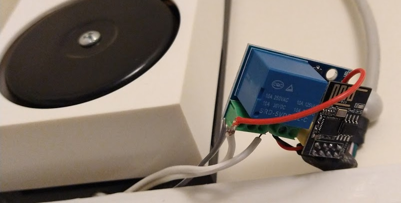
Once wired up it should look something like this:
Power
For my initial testing I connected the circuit board to an Anker battery pack and was astonished to see the system used 25% of an 2700mAH Anker per day! C size batteries totaling three volts still powered the doorbell itself.
Next steps - make it smart!
At the moment the doorbell is working exactly the same way as it used to - push a button and the bell rings. Next we'll make it smart by configuring some automations in Home Assistant.
Banner image: Proof of concept smart doorbell in position.
[1] The humidity sensor was wildly inaccurate.